










【 Must see for hands-on party 】
Unveiling the Working Principle of MCU: A Hardcore Journey from Code to LED Lighting
Are you curious about how a small MCU microcontroller can go from being "blank" to driving hardware? Today, we will use the essence of five minute animation, combined with the classic case of 8051 MCU, to take you to understand the working principle of MCU!
5-minute animation disassembly: How does MCU "command" hardware?

Scan the code to watch the video above and reveal the working principle of MCU microcontroller!
Startup: From "Blank" to "Ready"
Initial impression of the chip: The silicon wafer, bonding wires, and external program memory (8KB code) of the 8051 microcontroller form the basic hardware.
Power supply connection: The 5V power supply is connected through a transformer, and the chip is powered by 0V grounding (blue line) and 5V power supply (red line).
Initialization: Reset signal resets all internal components, program storage enable (PSEN) signal is pulled high, ready to read instructions.
Instruction Reading: Collaboration between Address and Data
Address and Data Transmission:
P0: The low 8-bit address is multiplexed with data, transmitting the address first (such as 0x0000), and then transmitting the instruction (such as LJMP).
P2: High 8-bit address, directly located to the storage space of the external EEPROM.
Address Latch (LE): Freeze the low 8-bit address when pulled low, ensuring that the P0 port can switch to the data bus and transmit instructions to the CPU.
Instruction execution:
The program counter (PC) starts from 0x0000 and reads and executes instructions, forming a "read execute" loop.
Hardware driver: How does the code light up the LED?
Assembly code parsing:
assembly
CLR P1.0 ; Pull pin P1.0 low (0V)
LJMP 0x100 ; Infinite loop, jump back to yourself
Circuit principle:
Pin P1.0 is connected to the LED cathode through a resistor, and the anode is connected to 5V.
The CLR P1.0 instruction causes P1.0 to output a low level, causing current to flow from 5V to the LED and turn on red light.
Key details:
PSEN signal: Pull down every time a command is read, activating the external EEPROM.
Address latch: The LE control line ensures address stability and avoids data conflicts.
YSPRINGMCU: from 8-bit to 32-bit, suitable for all scenarios
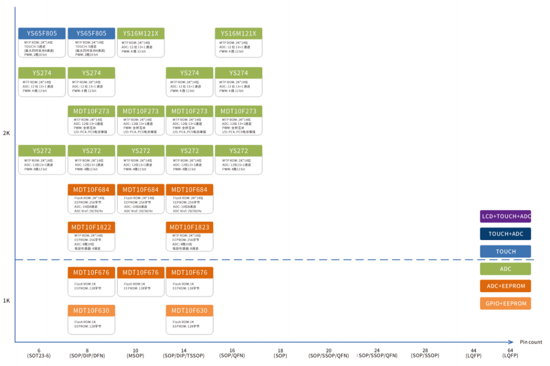
8-bit MCU:
Low cost: suitable for simple application of consumer small appliances.
Low power consumption: standby current is only μ A, extending battery life.
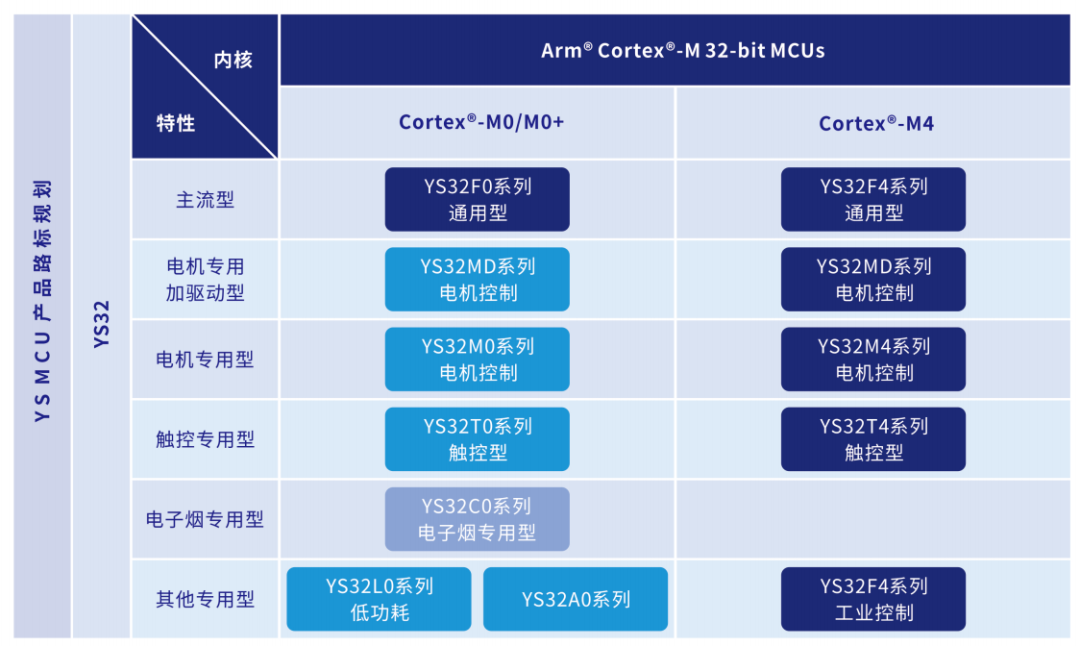
32-bit MCU:
High performance: With a clock frequency of 100MHz, it supports floating-point operations and can adapt to complex scenarios.
Strong peripherals: Integrated with USB, Ethernet, and CAN buses to meet the needs of the Internet of Things.
Full scene coverage:
From consumer electronics to Industry 4.0, from smart homes to automotive electronics, Huichun MCU connects everything with a single "chip". Welcome everyone to call us for selection and trial! Sales Hotline: 075586217885~


0755-86227153


